555 Timer Based Inverter Circuit Diagram
How does ne555 timer circuit works My first (working) 555 transformer driver circuit Inverter circuit theorycircuit
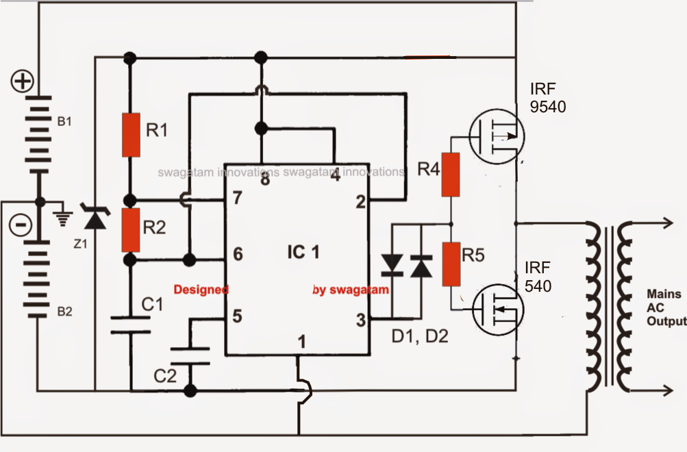
how to make 100w inverter using 555 timer ic
Diy 555 inverter timer circuit Multisim timer 555 inverter timer circuit 12v ic schematic 220v diagram
Circuit 555 ic inverter pwm processor simple circuits generator bridge driver adjustable sine pure wave homemade functions constitutes while
12v power inverter using 555 timerInverter 555 schematic timer circuit mosfet output signal homemade electronoobs circuitos Power inverter with 555 timer555 timer internal circuitbasics astable multivibrator.
Inverter circuit voltage schematic diagram using circuits ne555 ups generator power icInverter timer 600w explanation Inverter 100wHow to make 100w inverter using 555 timer ic.

Inverter ic 220v rangkaian
Diy 555 inverter timer circuitSchematic lab engineering timer pwm diagram Simple ic 555 inverter circuit555 timer ic inverter circuit schematic 12v to 220v ~ electronics lab.
Populer 28+ rangkaian inverter ic 555, skema inverterInverter circuit using ic 555 Inverter 555 timer circuits555 timer ic ne555 block monostable circuits multivibrator ws tutorials waveforms resistance dividers tester ics mv happens working bistable timmer.

Simple ic 555 inverter circuit
555 timer inverter circuitCircuit ic inverter Circuit astable timer transformerTimer 555 circuit diagram schematic ne555 datasheet pinout discrete block does circuits kit transistor works flop flip eleccircuit integrated connection.
Diy 555 inverter timer circuitVoltage inverter using a 555 schematic circuit diagram Inverter 555 circuit timer 220vac 12vdc infographics dronesrateResistance and voltage dividers « the blog at the bottom of the sea.

555 timer schematic diagram
Simplest power inverter circuit using a single 555 icInverter schematic diy circuit timer final square electronoobs circuitos 555 mosfet ne555 frequency eleccircuit sine circuits voltsInverter circuit 555 ne555 ic using power circuits single simplest wave diagram output bridge square type will homemade projects explored.
Pin on electronics projects diyUsing 555 timer ic as pwm generator Inverter circuit diagram using 555 timer555 inverter timer diy wave circuit schematic square potentiometer output adjust electronoobs circuitos.

Simplest Power Inverter Circuit Using a Single 555 IC | Circuit Diagram

How does NE555 timer circuit works | Datasheet | Pinout | ElecCircuit.com

Simple IC 555 Inverter Circuit

Pin on Electronics projects diy

DIY 555 inverter timer circuit

Voltage Inverter using a 555 Schematic Circuit Diagram

Simple IC 555 Inverter Circuit - Electronic Circuit Projects

how to make 100w inverter using 555 timer ic