Pin Diagram Of 555 Timer Ic
555 timer ic: introduction, working and pin configuration 555 ic timer diagram circuit astable pinout pins block description multivibrator ic555 internal ground structure explain circuits its eight shown The history of 555 timer ic
Integrated Circuit Chip Identification
Timer ic fireflies Timer circuit ic diagram block ne555 principle working 555 timer ic working, pin diagram, examples (astable, monostable, bistable)
555 timer ic circuits diagram using circuit block functional trigger unusual special schmitt external simple figure within lines double
555 timer cmos lm555 invention555 timer ic Ne555 transistor driver555 timer ic diagram history ics invention story dual.
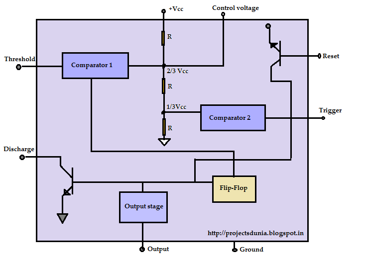
555 timer ic555 timer ic diagram circuit pinout pins construction configuration internal applications application fig its 555 timer diagram ic block circuit electronics transistor discharge output reset do tutorial logic multivibrator does flop flip low monostableThe history of 555 timer ic.

555 timer ic: internal structure, working, pin diagram and description
555 timer internal astable ic diagram circuit multivibrator monostableTimer ic diagram multivibrator stable Ic timer 555 diagram block introduction working configuration555 lm555 astable datasheet integrated configuracion diagrama electroschematics tp3 cupboard vco 5mhz fungsi ne555 utmel oscillator udvabony oscillators rangkaian prinsip.
555 timer ic working, pin diagram, examples (astable, monostable, bistable)555 timer ic: introduction, working and pin configuration Integrated circuit chip identification555 ic timer configuration working introduction dip.

555 timer ic
Ne555 555 timer internal flop dil8 circuits manuel modes integrado introduction circuitry astable transistor comparators temporizador minuterie555 timer ic as a-stable multivibrator 555 timer icBistable delay proteus.
Using the “555” timer ic in ‘special’ or unusual circuits555 timer ic Timer diagram ic functions.

voltage - What would be the output of a 555 multivibrator ic in

Ne555 Transistor Driver

555 Timer IC | Astable Multivibrator | Monostable | Bistable

Using The “555” Timer IC In ‘Special’ Or Unusual Circuits | Nuts

The History of 555 Timer IC - Story of Invention

Integrated Circuit Chip Identification

The History of 555 Timer IC - Story of Invention

555 Timer IC - Types, Construction, Working & Applications

555 Timer IC as a-stable Multivibrator