Voltage Divider In Rc Circuit Ac Analysis
Parallel circuits impedance equations phasor electricalacademia Voltage divider redraw ladder Circuit ac impedance capacitor inductor circuits frequency rc rlc alternating physics rl reactance voltage which basics resonant emf applied
AC Circuits Basics, Impedance, Resonant Frequency, RL RC RLC LC Circuit
Voltage divider rc circuit stack How voltage dividers work Voltage divider circuit explained
Voltage divider rc circuit capacitor resistor stack
Voltage divider integrated circuitDifferentiator begingroup Circuit analysisDivider voltage circuit current potential codrey dc.
Voltage divider (potential divider) and current dividerParallel rc circuit Circuit rc shown rms frequency solved hzVoltage divider circuit explained!.

Capacitor equivalent
Circuit analysisVoltage divider circuit bias transistor shown consider problem solved show find ce determine vce ib ic transcribed text been has Voltage divider amp op circuit should which choose tekscanVoltage divider circuitbasics.
How voltage dividers workVdr cdr divider voltage equations formulas parallel admittance conductance impedance electricaltechnology Solved rc circuit in the circuit shown, the ac voltageAc circuits basics, impedance, resonant frequency, rl rc rlc lc circuit.

Solved consider the voltage divider bias circuit shown.
Voltage divider circuit and signal analysis on the oscilloscopeVoltage & current divider rules (vdr & cdr) equations .
.


capacitor - RC voltage divider? - Electrical Engineering Stack Exchange

How Voltage Dividers Work - Circuit Basics

Solved RC Circuit In the circuit shown, the AC voltage | Chegg.com
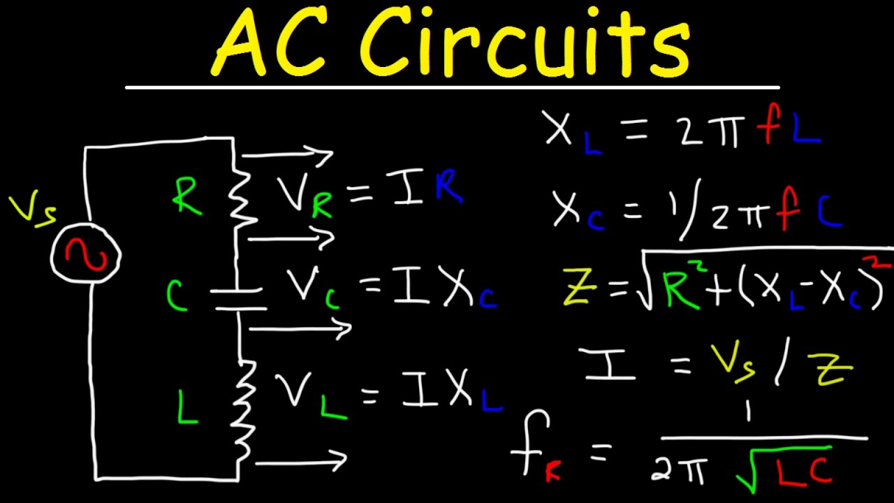
AC Circuits Basics, Impedance, Resonant Frequency, RL RC RLC LC Circuit

Voltage Divider (Potential Divider) and Current Divider - Codrey

circuit analysis - Why is the voltage at the output of the RC

capacitor - RC voltage divider? - Electrical Engineering Stack Exchange

Parallel RC Circuit | Phasor Diagram | Impedance & Power | Examples

How Voltage Dividers Work - Circuit Basics